

Device alarms (also referred to as hardware alarms) can be configured to activate an LED light on a logger to flash, and/or an audible alert to sound on RF2000A series loggers, when readings fall outside of user-specified thresholds.
Device alarms can be enabled and configured via the MadgeTech 4 software. The alarm configuration menu will vary somewhat depending on the model of logger being used, but the basic steps for configuring the alarms will be similar. Below are descriptions of features that are common to all models, as well as additional descriptions of features that are specific to particular models.
Common Features
Basic setup of device alarms can performed using the following steps:
Note: The logger must be in the “Stopped” status to make changes to the alarm settings. It is recommended to stop the logger and download data (if necessary) prior to following the steps below.
1. Select the desired logger in the “Connected Devices” panel of MadgeTech 4.
2. Click the “Properties” button in the “Device” toolbar.
3. Select the “Alarm” tab in the properties menu.
4. Check the “Enable alarm settings” checkbox, and/or the desired threshold checkbox(es).
5. Enter thresholds by typing the values directly into the applicable threshold text fields, or by adjusting the sliders to the right of the text fields (not available for all models).
6. Enter delay time and check or uncheck “Use cumulative alarm delay” box (both optional; not available on all models).
7. Click “OK.”
8. Alarms will be active when the logger is started.
Detailed descriptions of the fields in the “Alarm” menu are below.
Alarm Thresholds/”High” and “Low” fields: All models of loggers that have device alarms have “High” and “Low” text fields. These are the alarm thresholds. The device will alert if the value recorded by the logger rises above the value entered in the “High” field, or falls below the value entered in the “Low” field.
The desired value for the high or low threshold can be typed directly in the text box for each of the fields. For some logger models, there is also a slider on the right-hand side of the menu that can be used to adjust the high and low thresholds. When adjusting the thresholds with the slider, the updated values will be reflected in the text fields.
When entering a threshold value in the text field, the software may automatically change the entered value by a small amount. For example, if entering an integer, the software may add a decimal value, and the updated number will be slightly higher or lower (typically by a few tenths or hundredths) than the originally entered value. This is normal, and is caused by the software factoring in the calibration and resolution of the logger to determine viable display values, which are in turn used for the alarm value. In addition, the software uses Celsius as a native unit for temperature, so if the alarms values are set using Fahrenheit, MadgeTech 4 will be converting to the Fahrenheit values from Celsius. As a result of these minor changes, the value entered by the user may need to be adjusted slightly, to ensure that the software-adjusted value will still meet the threshold requirements of the alarm.
“Enable Alarm Thresholds” checkbox: For models that have the “Enabled Alarm Thresholds” checkbox, the box must be checked to enable the alarms. If the box is unchecked, the alarms will not alert, even if the alarm thresholds have been updated.
Some models will feature both the “Enable Alarm Thresholds” checkbox, as well as individual checkboxes for each “High” and “Low” alarm threshold (also, for high and low warnings; see the “IFC300” section below). In these cases, the “Enable Alarm Threshold” box, as well as the checkbox for each desired threshold must be checked for the logger to alert.
For loggers that have only the “Enable Alarm Thresholds” checkbox, both the high and low thresholds will be enabled if the box is checked. However, if only a single threshold is desired, an unrealistically high or low value can be entered in the undesired field. For example, if it’s desired that a logger only alert when it exceeds a high temperature threshold, a temperature of -200 °C (-328 °F) could be entered for the low threshold. Assuming that the logger is used in an environment where the temperature would never drop below -200 °C, the logger should then never alert due to the readings dropping below the low threshold. Conversely, an unrealistically high temperature could be entered for the high threshold if it is desired that the logger only alert when the readings drop below the low threshold.
Clear Alarm button: When an alarm on a device has been triggered, the “Alarm Status” in the alarm properties menu will change from “Clear” to “Active.” Click the “Clear alarms” button to reset the alarm status to “Clear.”
The “Alarm warning” status and “Clear warning” button will work in the same manner.
For the RF2000A series, the LED light and/or audible alert on the device can be reset by clicking any of three buttons on the face of the logger.
Delay field: Alarm delays can be enabled by entering a time (hours, minutes, seconds) in the “Delay” text box. When a delay time is entered, the logger will not alert unless the reading is outside the enabled thresholds for the specified amount of time. This is useful when it is acceptable for readings to fall outside of the threshold for a brief period, but prolonged periods of readings outside of the thresholds are a concern.
For example, if a reading outside of the specified thresholds is only a concern if the reading remains outside of the thresholds for 5 consecutive minutes or more, a time of “0 h, 5 m, 0 s” can be entered in the “Delay” field. When using the alarm delay feature, it is recommended to use a delay time that is longer than the reading interval being used, to ensure that the logger is taking readings frequently enough to detect readings outside the threshold within the specified delayed time. Using the previous example, if an alarm delay of 5 minutes has been set, but the logger is using a 10 minute reading interval, the actual value of the unit being measured could potentially fall outside the alarm thresholds for 5 minutes in between consecutive readings, and the logger would not alert as the alarms are based on the reading values only. In this example, if a one minute reading interval is used instead, then an alarm with a 5-minute delay time will trigger if the reading values are outside of the enabled thresholds for 5 consecutive readings.
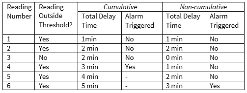
Cumulative Alarm Delay: Some models also provide the “Cumulative alarm delay” option. When an alarm threshold has been enabled and a delay time has been entered, checking the “Use cumulative alarm delay” checkbox will prevent the alarm delay from resetting when a reading falls back within the alarm threshold. When the box is unchecked, each time a reading falls within the threshold, the total delay time will reset to zero, effectively meaning that out-of-threshold reading values must be consecutive to be counted toward the delay time. With the “Cumulative alarm delay” box checked, all readings outside the threshold will be added to the cumulative delay time, and the logger will alert once the cumulative time exceeds the specified delay time.
Model-Specific Features
IFC300 Series (CryoTemp, LyoTemp, TransiTempII): In addition to high and low alarm thresholds, logger models that use the IFC300 interface also feature high and low warning thresholds. Warnings are enabled in the same manner as alarms, by checking the appropriate “Warn high” and/or “Warn low” checkbox and entering the desired value.
Warnings are intended to indicate when a reading value is approaching, but has not yet reached, the corresponding alarm value. When both alarms and warnings are enabled, the warning thresholds must be within the alarm thresholds; that is, the “Warn high” value must be lower than the “Alarm High” value, and the “Warn low” value must be higher than the “Alarm Low” value.
When warnings are triggered, the yellow “Warn” LED light will flash on the face of the logger. When an alarm is triggered, the red “Alert” LED will flash (and the yellow light will no longer flash).
RF2000A Series: Several RF2000A series loggers have multiple channels (thermocouple and ambient channels; temperature and humidity channels, etc.) On multichannel loggers, there will be a separate section in the alarm menu for each channel. Always ensure that the high/low field is in the section for the appropriate channel when enabling/disabling alarm thresholds and entering threshold values.
See the chart below for a comparison between alarm behavior when the “Use cumulative alarm delay” box is checked (cumulative), and unchecked (non-cumulative):
For additional information on the types of alarms available for MadgeTech equipment, see the “MadgeTech Alarm Types” article.
