I’m having trouble with my Interface cable (IFC200, IFC202, IFC300, IFC400).
Please follow the steps below to install the USB drivers:
The interface cable should be unplugged.
Download the latest USB drivers from the MadgeTech software download page: MadgeTech 4 Software | MadgeTech Save this in a location that is easy to find such as the Desktop or Downloads folder.
Locate the “USB_Drivers_run_bat” zip file that you just downloaded. Right-click the file and select Extract all and follow the prompts to extract the contents of the zip file to a folder.
Once it is successful, plug the IFC back in (preferably to a different USB port than before) and wait for the blue light to come on.
Launch the Software.
Attach the data logger to the interface cable or docking station.
Once the USB drivers are installed, the interface should be shown in File–>Options–>Communications, under Detected Interfaces. If the interface is still not shown, or the loggers are still not communicating in the Connected Devices panel, contact [email protected] for additional assistance.
The software displays “No devices are connected. Why are my devices not appearing?” – MadgeTech 4
The software displays “Unable to find an active device!” – MadgeTech 2
This generic error occurs when a data logger fails to connect to the software. There are several potential causes.
1) The interface cable may not be plugged into the computer.
2) The data logger may not be plugged into the interface cable.
3) The battery in the data logger may be depleted.
4) The product may not be supported by the version of software being used, if it is not the latest version. Typically, the software will display an error or notification. Later versions are backwards compatible, so there is no drawback to having the latest version. The latest version of the software and drivers are available on our software download page: https://www.madgetech.com/software/madgetech-4-software/. To determine the latest software version in MadgeTech 4, go to File > Options > About, or in MadgeTech 2, go to Help > About. In almost all circumstances, MadgeTech recommends that MadgeTech 2 users update to MadgeTech 4.
5) If the interface cable is an IFC200/IFC202/IFC300/IFC400/RFC1000, the USB drivers may not be installed properly, or may be out of date. Check to see if a blue LED is lit on the interface (not applicable to RFC1000).
If the interface is an IFC200 (flash drive model), it is plug and play and there is no need to install the device drivers. If the interface is the older IFC200 R1 (Rectangular box with two wires), IFC202, IFC300, IFC400, or a RFC1000, install the USB drivers first. Disconnect the IFC from the computer, download the USB drivers from the software download page above, extract the files from the downloaded ZIP folder, and run the PreInstaller.exe from within the new folder. This will install the updated drivers. Connect the IFC to the computer and Windows will apply the driver. At this point, the blue LED should light up on the IFC. The RFC1000 has a red LED to indicate power and a flashing green LED to indicate communication with wireless logger.
MadgeTech 4:
Verify the interface cable is correctly installed, by checking that it shows up under Detected Interfaces in File > Options > Communication. Check the box labelled “Search for devices using USB interfaces.” Connect the logger to the IFC. If successful, the logger appears in the Connected Devices panel.
Claim Wireless loggers from the list of active data loggers. Uncheck the box labelled “Only show claimed wireless devices.” Select the desired logger from the list and click the Claim icon.
MadgeTech 2:
Select Auto Configure Port from the Communications menu to communicate with the logger. If successful, the software displays “Found a <logger model> on <communication port>” where the logger model is the name of the type of data logger, and the communications port is the one used by the IFC. If unsuccessful, manually connect the logger. Go to the Communications Menu and select the Baud Rate specified on the device. Go to Communications and select the Comm Port. Typically, the Comm Port is USB1 if the interface is a IFC200/202/300/400. If using an IFC110, the COM# for the Communication Port will be specified in the Ports section of Device Manager.
For remaining issues, please contact [email protected]. Include as much information as possible by listing all attempted troubleshooting. Specify the data logger model, the interface cable, the PC operating system, the software version and drivers (File > Options > About in MadgeTech 4, or Help > About in MadgeTech 2).
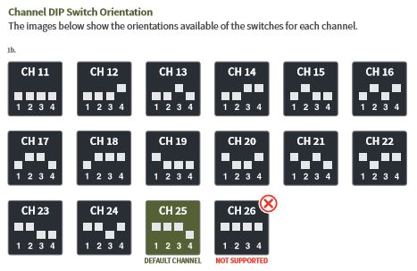
There are dip switches on the RFC1000s, the original larger model RFOTs, and all models of Therm-A-lerts. There are four switches together labeled 1, 2, 3, and 4. These dip switches are what you use to configure the wireless channel that the wireless system operates on.
For most customers the default (Channel 25) setting—1,2,3 UP and 4 DOWN—should be suitable. However, if you are having signal strength issues or wireless interference, in otherwise good locations you may want to try switching all of your loggers and RFC1000s to a different channel by changing the dip switch configuration. If some of the loggers or RFC1000s are configured with different combinations, they will NOT communicate with each other. This means if you wanted to set up two discrete networks of loggers that were separate from each other, you could simply set up some of them on one channel, and the rest on another.
These switches should not be confused by the wireless On/Off switch, which is a small black switch that can be set to (1) for Wireless mode or (0) for Stand-Alone mode.
When changing the channels, wireless should be toggled off, and toggled back on again after changing the channels. The channel change will not work properly unless this reset is performed.