

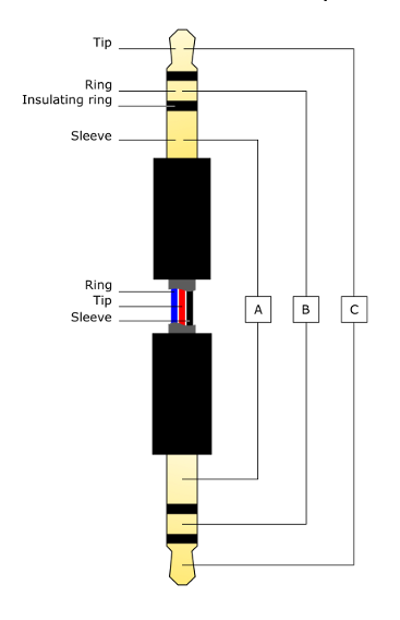
Stereo cables have black or colored plastic insulating rings that separate a stereo cable jack into three separate segments, called the tip, ring, and sleeve.
These three segments are then attached to three wires that are electrically separated with insulation, allowing each channel to send its own signal. Through flexing of the cable over time, the insulating material can split or separate and expose the bare wire of the three channels. This exposure can result in crosstalk, which will interrupt the communication between the IFC200 and data loggers.
It is also possible that the metal of the wire has separated from the jack itself, or separated somewhere inside of the length of cable. This would cause complete communication loss along a single segment.
A multimeter set to measure resistance in Ohms (Ω) can be used to test if either of these issues have occurred. To test for continuity and crosstalk, connect the test leads of the multimeter to each end of the stereo cable on the identical opposing segment.
When testing each segment, there should be a trivial amount of resistance measured from opposing tips, rings, and sleeves respectively. However, there should be no measured resistance between tip-to-ring, tip-to-sleeve, or ring-to-sleeve. If there is any measured resistance between these segments, or if there is no measured resistance between one of the three opposing segments of the cable, then it would be advisable to replace the stereo cable entirely.
When replacing the stereo cable, it’s important to make sure the replacement jack is identical to the original, in that it has three metal segments separated by two insulating rings.
